Active Electronically Scanned Array (AESA) radar systems generate immense heat from hundreds of densely packed T/R modules. Effective thermal control is now a decisive factor in radar performance, reliability, and service life. Vapor chamber technology—a phase‑change cooling solution—has emerged as a core enabler, offering exceptional heat spreading and temperature uniformity. This article reviews the working principles, integration approaches, real‑world use cases, and emerging trends of vapor chambers in AESA radar, providing a practical reference for engineers and system designers.
1. Introduction
AESA radar represents the cutting edge of modern detection systems. Its performance continues to climb as power levels and component densities increase. Yet this progress brings a critical bottleneck: heat dissipation. Each AESA array contains hundreds or even thousands of T/R modules, each housing high‑power microwave chips that generate concentrated heat within a confined space. Without efficient cooling, chip temperatures rise rapidly, degrading radar accuracy, reducing detection range, and shortening equipment lifespan.
Conventional metallic heat spreaders—copper or aluminum—often fall short in meeting the stringent thermal demands of next‑generation arrays. Vapor chambers, however, offer a compelling alternative. By leveraging a two‑phase evaporation‑condensation cycle, they achieve effective thermal conductivity far exceeding that of solid metals, while also equalizing temperature across large surfaces. As a result, vapor chambers are becoming a standard solution in AESA thermal management.
2. How Vapor Chambers Work and Why They Matter
2.1 Operating Principle
A vapor chamber is essentially a flat, two‑dimensional heat pipe. Its internal cavity is evacuated and filled with a small amount of working fluid, with a wick structure lining the inner walls. When heat from T/R modules enters the evaporator zone, the fluid vaporizes. The vapor rapidly spreads across the entire chamber, carrying thermal energy to the cooler condenser region. There, it condenses back to liquid, releasing latent heat. The wick then draws the liquid back to the hot zone via capillary action, completing the cycle.
This continuous phase‑change loop gives vapor chambers an effective thermal conductivity that is several times higher than that of copper or aluminum—and it does so in a thin, lightweight form factor.
2.2 Key Advantages for Radar Systems
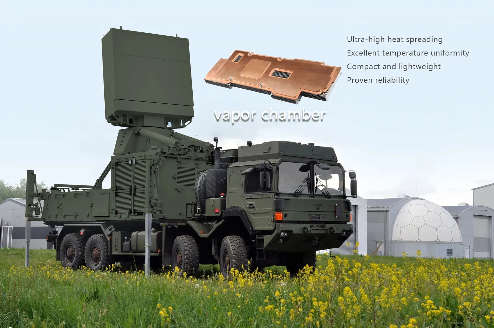
- Ultra‑high heat spreading – Vapor channels can quickly move heat away from localized hot spots, eliminating the thermal resistance that plagues solid spreaders.
- Excellent temperature uniformity – By distributing heat evenly across the board, vapor chambers prevent uneven temperature gradients that can cause beam‑pointing errors and degrade radar performance.
- Compact and lightweight – Their slim profile supports the trend toward smaller, more integrated radar arrays.
- Proven reliability – With no moving parts, vapor chambers offer long operational lifetimes, even under harsh military or aerospace conditions.
3. Integration Approaches in AESA Radar
3.1 Direct Cooling of T/R Modules
The most straightforward application places a vapor chamber directly beneath a cluster of T/R modules. Thermal interface materials bridge the gap, ensuring good contact. The vapor chamber collects the waste heat from multiple modules, spreads it uniformly, and transfers it to secondary cooling systems—such as forced air or liquid loops.
Advanced designs incorporate high‑conductivity materials in a honeycomb pattern within the vapor chamber to further improve through‑plane and in‑plane heat transfer, making them particularly suitable for phased‑array antenna applications.
3.2 Embedded in Digital Sub‑array Modules
Modern AESA architectures adopt a modular “sub‑array” approach. Here, vapor chambers are integrated directly into the digital sub‑array assembly. Heat sources—including RF power amplifiers, power supplies, and digital processors—are all thermally coupled to the vapor chamber. The phase‑change medium evaporates on the hot side and condenses on the cold side, where airflow or liquid coolant removes the heat.
Recent studies have validated this concept through prototype testing, showing that two‑phase vapor chambers effectively address the conflicting challenges of small footprint, high heat load, and distributed heat sources within sub‑arrays.
3.3 Hybrid Thermal Architectures
Vapor chambers rarely work alone. They are often paired with other cooling technologies to form hybrid systems:
- Vapor chamber + air cooling – Finned heat sinks and fans are attached to the condenser side. This combination increases overall heat rejection efficiency while reducing fan speed and noise. In one vehicle‑mounted millimeter‑wave radar design, this hybrid approach lowered the peak chip temperature by nearly 10°C compared to a conventional air‑cooled heatsink.
- Vapor chamber + liquid cooling – A liquid‑cooled cold plate is placed on the condenser side for even higher heat removal rates, ideal for high‑power ground‑based or shipboard radars.
- Vapor chamber + heat pipes + fins – Multiple heat pipes of varying lengths connect the vapor chamber to a remote fin stack, offering flexible routing for space‑constrained arrays.
- Vapor chamber + phase‑change energy storage – For pulsed or transient high‑power operation, a separate phase‑change material absorbs peak heat loads, smoothing out temperature spikes and reducing the burden on active cooling.
3.4 Maintaining Temperature Consistency in Tile‑type Arrays
In tile‑array configurations, where components are laid out in a planar fashion, vapor chambers help ensure that all elements operate at nearly the same temperature. Numerical simulations indicate that while increasing the chamber’s thermal conductivity may not dramatically lower absolute temperatures, it significantly improves temperature uniformity—a critical factor for stable electrical performance across the aperture.
4. Real‑world Implementation Examples
4.1 Vehicle‑mounted Millimeter‑Wave Radar
Engineers at the 38th Research Institute of China Electronics Technology Group developed an integrated vapor‑chamber‑and‑fin air‑cooling solution for a vehicle‑borne millimeter‑wave radar. Through simulation and optimization, they chose a fin height of 30 mm and a spacing of 3 mm, achieving a maximum chip junction temperature of 141.1°C—well within the safe limit. The design reduced the hotspot temperature by 9.8°C relative to a conventional aluminum heatsink.
4.2 Phased‑Array Antenna Test Module
A patent‑protected test module combines an antenna board, a vapor chamber, and a finned heat spreader. Thermal pads bridge the antenna to the vapor chamber, and the fins are mounted on the back side. This simple but effective stack‑up provides excellent heat spreading during lab testing and validation.
4.3 High‑Integration Digital Sub‑array for Next‑Gen Radar
For an open‑architecture AESA radar, researchers designed a high‑density digital sub‑array using a two‑phase vapor chamber as the primary thermal spreader. The prototype passed thermal tests, and the measured data guided further optimization of thermal resistance paths and structural layout—proving the practicality of this approach in production systems.
4.4 Flat‑Panel AESA Antenna
A compact, low‑profile flat‑panel antenna design stacks the microstrip radiating layer, a vapor chamber (with embedded heat pipes), the T/R module array, and a backplane. The vapor chamber, directly attached to the front of the T/R modules, enables natural convection cooling without adding bulky heatsinks, thereby preserving the low‑profile form factor.
5. Emerging Materials and Manufacturing Innovations
5.1 Graphite‑Aluminum Composites
Advanced composite materials, such as graphite‑reinforced aluminum, offer excellent in‑plane thermal conductivity combined with low density. Domestic manufacturers have developed proprietary processes to produce these composites, which are now being used in vapor chamber baseplates and panels for satellite radars, missiles, and aircraft. The high directional conductivity makes them particularly attractive for spreading heat across large array areas.
5.2 Additive Manufacturing (3D Printing)
Additive manufacturing is opening new possibilities for vapor chamber fabrication. Researchers have successfully printed capillary wick structures directly onto chamber walls, enabling monolithic, integrated designs that eliminate bonding joints and reduce thermal interface resistance. This approach simplifies production, lowers cost, and enables complex geometries that are difficult to achieve with conventional methods.
5.3 Diamond/Copper Composites
For extreme power densities, diamond‑copper composites—which boast thermal conductivity even higher than pure copper—are being studied as potential vapor chamber materials. While still in the research phase, these composites could push the boundaries of heat spreading capability in future ultra‑high‑power AESA systems.
6. Future Trends and Outlook
6.1 Coping with Ever‑Rising Power Densities
As AESA radars evolve toward higher frequencies, wider bandwidths, and greater miniaturization, the heat flux from T/R modules continues to climb—exceeding 50 W/cm² in some designs. Vapor chambers must keep pace through improved wick structures, optimized fluid selection, and thinner profiles.
6.2 3D Stacked and Heterogeneous Integration
Advanced packaging trends, such as chiplet and multi‑chip modules, demand ultra‑thin, flexible, or even 3D‑shaped vapor chambers. Three‑dimensional vapor chambers—with multiple evaporator and condenser zones—are already under development to handle complex thermal pathways in densely packed electronic assemblies.
6.3 Intelligent Thermal Management
Future radar systems will likely incorporate smart thermal controls, where vapor chambers work in tandem with phase‑change storage and active cooling loops. Embedded sensors and adaptive algorithms will adjust cooling capacity in real time, responding to both transient pulses and sustained high‑power operation.
6.4 Growing Market Adoption
Industry analysts forecast the global vapor chamber market to reach $1.2 billion by 2025, with military radar applications being a significant growth driver. As costs decrease and manufacturing matures, we can expect even wider adoption across land, sea, air, and space platforms.
7. Conclusion
Vapor chamber technology has moved from a niche solution to a cornerstone of AESA radar thermal management. Its ability to spread intense heat loads quickly and evenly—while remaining compact and reliable—makes it indispensable for modern phased‑array systems. From module‑level cooling to full‑array integration, vapor chambers have proven their worth in numerous fielded designs. With ongoing advances in materials, additive manufacturing, and intelligent controls, vapor chambers will continue to evolve, enabling the next generation of higher‑performance, more reliable radar systems for defense and civilian applications alike.