Modern high‑power electronics push thermal designers into a tight corner. CPUs, GPUs, gaming hardware, data‑center boards and compact consumer devices all generate concentrated heat flux that standard solid‑metal heat sinks often struggle to handle. Many engineers turn to vapor chamber cooling for better heat spreading — but vapor chambers are not a “one‑size‑fits‑all” fix.
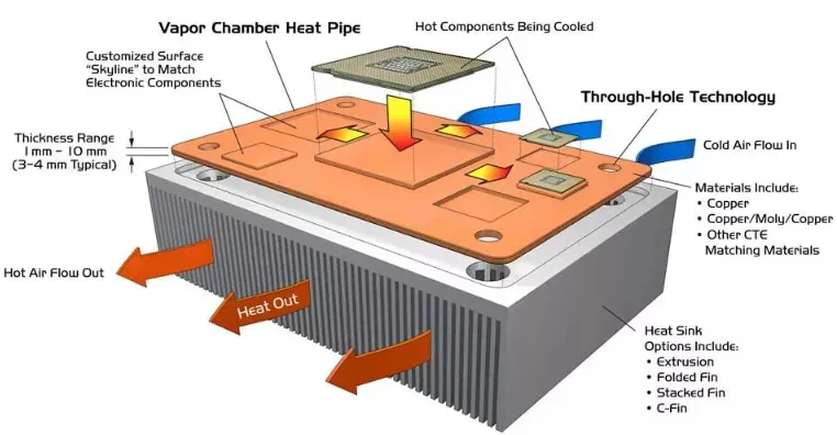
In decades of building custom thermal assemblies, our engineering team has seen projects succeed and fail based on simple early‑stage design choices. This article walks through how vapor chambers work, key differences compared to heat pipes, available chamber variants, practical performance limits, and real‑world trade‑offs you should weigh before specifying a vapor chamber into your bill‑of‑materials.
What Exactly Is a Vapor Chamber?
A vapor chamber is a flat, sealed two‑phase heat spreader, most commonly built from copper housing a small charge of de‑ionized water as the working fluid. Inside the chamber sits a wick structure — typically sintered copper powder or etched grooves — that drives liquid back toward the heat source through capillary force.
The operating cycle is straightforward in theory, but sensitive to manufacturing quality in practice:
1. Heat from CPU/GPU or other hot components transfers through the base plate, boiling the internal liquid.
2. Generated vapor expands rapidly across the flat cavity, distributing heat across the full chamber surface.
3. When vapor reaches cooler condenser zones, it condenses back into liquid and releases thermal energy.
4. The wick pulls condensed liquid back to the evaporator area to restart the cycle.
Important point to remember: a vapor chamber spreads heat efficiently, but it does not reject heat to ambient air by itself. It must pair with fins, heat sinks or cold plates to exhaust heat out of the system. Many first‑time designers overlook this point and end up disappointed with overall system thermal results.
Vapor Chamber vs Heat Pipe: When Should You Pick Which?
It is easy to mix vapor chambers and heat pipes, as both rely on evaporation‑condensation two‑phase cooling. The core difference lies in heat movement geometry.
Heat pipes are tubular components built for one‑dimensional heat transport: they move heat from point A to point B along the tube axis. They work great when you need to carry heat away from a hot component toward a remote fin stack.
Vapor chambers deliver true two‑dimensional heat spreading. If you have a concentrated hot‑spot sitting on a small die area, a vapor chamber can flatten temperature gradients across the whole plate surface. This makes hot‑spot suppression its biggest strength.
In our shop, we frequently see customers select heat pipes for simple point‑to‑point heat transfer, while turning to vapor chambers when their design suffers from severe local hot‑spots or when mechanical space calls for a flat thin profile. Sometimes we combine both technologies within one assembly for complex board layouts.
| Item | Vapor Chamber | Traditional Heat Pipe |
|---|---|---|
| Heat transfer mode | 2‑D planar spreading | 1‑D linear transport |
| Hot‑spot handling | Excellent | Good, limited by layout |
| Form factor | Flat plate | Round / flattened tube |
| Typical use case | Hot‑spot mitigation, compact device heat spreading | Transport heat to distant heat sink |
Common Vapor Chamber Types and Typical Use‑Cases
Not all vapor chambers are built the same. Four main constructions show up across our customer projects, each with clear pros and target applications.
Ultra‑Thin Vapor Chambers (<1 mm thickness)
Ultra‑thin vapor chambers target space‑constrained compact hardware. Mobile‑form‑factor devices, handheld equipment and slim consumer electronics rely on this variant.
Thinning a chamber brings manufacturing challenges. Wick geometry and internal cavity volume become very limited. Performance drops if you push power beyond the design window, so power budget must be locked‑in early in product development.
3D Vapor Chambers
3D vapor chambers implement multi‑layer, complex internal cavity structures. They handle higher power density for gaming systems, high‑performance computing boards and power‑heavy industrial electronics.
These units require complex tooling and thorough thermal validation. They are not a low‑cost option, but they solve thermal problems where flat 2D chambers hit performance ceilings.
Two‑Piece Modular Vapor Chambers
Two‑piece vapor chambers separate evaporator and condenser sections, joined during assembly. This modular approach gives mechanical engineers more layout freedom.
When your product has unusual mechanical partitioning or custom enclosure constraints, this variant can simplify integration. It adds assembly‑related sealing requirements that must be addressed during prototype validation.
Low‑Cost One‑Piece Vapor Chambers
Mass‑produced one‑piece vapor chambers serve mainstream consumer‑grade products. They deliver reliable baseline thermal performance at more approachable unit costs.
Cost savings come from standardized tooling. Custom geometry options are limited, so your mechanical envelope needs to align with existing form factors.
Real‑World Factors That Define Vapor Chamber Thermal Performance
From our prototype‑testing experience, theoretical datasheet numbers rarely tell the full story. Five practical factors dominate real‑world results.
1.Wick and working‑fluid design
Wick structure defines capillary pumping limits. Poor wick layout will cause liquid starvation at high heat loads, killing performance even with good raw materials. Matching working fluid to your operating‑temperature window is equally critical.
2.Material selection
Most vapor chamber base plates and wicks use copper for high thermal conductivity. Fins can be copper or aluminum. Pairing vapor chamber with aluminum fins delivers a good balance of thermal performance and lower overall weight.
3.Contact interface quality
Perfect vapor chamber performance gets wasted if you leave air gaps between component and chamber base plate. Proper mounting pressure plus high‑quality thermal interface material is non‑negotiable. We have seen 10‑15 °C delta difference just from bad interface installation.
4.Effective heat‑source contact area
Maximize contact footprint between heat source and vapor‑chamber base. Small‑area hot‑spots push flux high and can exceed chamber operational limits, even if total system power looks reasonable on paper.
5.Full‑system thermal design
Never evaluate vapor chamber in isolation. It works as part of a larger thermal system: fins, fans, airflow paths all define final component temperatures. A great vapor chamber cannot rescue a poorly‑designed airflow environment.
Vapor Chamber Advantages and Practical Drawbacks
Every thermal solution carries trade‑offs, and vapor chambers are no exception.
Key Advantages
- Outstanding hot‑spot reduction and uniform temperature distribution across the spreader surface
- Thin mechanical profiles, well‑suited for compact hardware designs
- Lighter than solid‑copper heat spreaders of equivalent dimensions, with superior thermal spreading capability
- Customizable wick and geometry options to fit diverse project requirements
- Supports longer component lifespan by avoiding sustained extreme local temperatures
Real‑World Drawbacks
- Higher unit cost compared against solid copper spreaders or standard heat pipes, driven by complex sealing and internal wick fabrication
- Specialized manufacturing knowledge required; not every thermal vendor can deliver consistent, reliable vapor‑chamber builds
- Performance boundaries exist: every chamber has maximum heat‑load limits. Overspec or wrong operating orientation will degrade performance.
Is Vapor Chamber Cooling Right For Your Project?
Choose vapor chamber cooling when you face these scenarios:
- Your design has sharp hot‑spots from high‑flux semiconductors
- You need even temperature distribution across a flat surface
- Mechanical constraints demand a thin heat‑spreader profile
It may not be the best fit if your project is strictly cost‑limited and heat‑flux levels remain moderate. In such cases, heat pipes or solid copper plates can deliver acceptable performance at lower expense.
Before freezing your design, work through thermal simulation and prototype testing. If you are unsure which two‑phase cooling approach fits your requirements, talk with our thermal engineers early in your design cycle. Early consultation avoids costly hardware rework later in product development.
Frequently Asked Questions
Q: Do vapor chambers require maintenance?
No. Vapor chambers are hermetically sealed assemblies. Under normal operating conditions they operate maintenance‑free for the equipment service life. Physical damage such as puncture will break the sealed system.
Q: Can vapor chambers replace liquid cold plates?
Not directly. Each serves different purposes. Vapor chambers excel at planar heat spreading. Cold plates are intended for high‑total‑power heat removal via liquid coolant. In high‑power systems, they can work together in one thermal stack‑up.
Q: Can I retrofit a vapor chamber into an existing product?
Retrofit is possible only if mechanical envelope, mounting structure and overall thermal system can accommodate it. Most gains happen when vapor chamber is considered during initial product design phase.
Conclusion
Vapor chamber cooling is a powerful two‑phase thermal solution, but it is not magic. Good outcomes come from understanding its operating boundaries, matching chamber type to your power and mechanical constraints, and treating it as one component within your full thermal system.
At Radian Thermal Products, our engineering team designs and manufactures custom vapor chamber heat sinks for data‑center hardware, gaming platforms, medical equipment and high‑end consumer electronics. If you want to explore vapor‑chamber options for your next project, reach out for a technical review and quote.