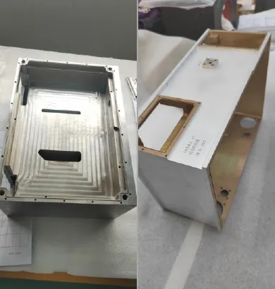
Overview
In a liquid-cooled chassis, the coolant flow paths live in the chassis walls themselves and stay in direct thermal contact with the heat sources. That makes the enclosure a structural part and a thermal management part at the same time.
A liquid-cooled chassis holds one or more liquid-cooled plates and forms an electronics enclosure with integrated cold walls. Heat moves straight from high-power boards into the coolant; the coolant then travels through the walls to a remote location where the heat is dissipated.
When you have several boards to cool in one system, the liquid-cooled chassis is a more integrated answer than wiring up multiple standalone liquid-cooled plates.
Working Principle
A circulation pump drives coolant, pre-chilled by an external chiller, through the cold plates inside the chassis. The coolant absorbs heat from the electronic components during operation, carries it back to the external cooling source, and releases it there. The loop runs continuously to keep component temperatures within spec.
Key Advantages
Light and compact
Lower system weight and a tighter footprint than a stack of standalone plates, at a lower overall cost.
Fully sealed housing
Waterproof, moisture-proof, and dust-tight, with electromagnetic shielding built in.
High heat flux capability
Strong thermal conductivity and heat spreading handle high-power boards and dense heat loads.
Even flow, no dead zones
An internal fin structure distributes coolant uniformly across the cold plate, so heat is pulled off evenly.
Quick-connect fittings
Tool-free hookup speeds up installation and field service.
Manufacturing Process
Component machining → Vacuum brazing / Friction stir welding → Airtightness test → Precision machining → Final assembly / Electron-beam welding (special tooling) → Final machining → Airtightness & pressure test → Drying → Helium mass spectrometry leak test (pos./neg. pressure) → Additional tests → Surface treatment
Design Flexibility
Flow path options
Internal flow paths range from simple tubes bonded to the structure to complex channel layouts. Contact area, flow rate, and pressure drop are optimized against your target specs.
Build methods
Aluminum die casting, sheet-metal bending, welding, dip brazing, and vacuum brazing are all available, so the manufacturing route matches your cost and performance targets.